Factor group
Light, Optics, Temperature & Camera Artefacts
The biggest single source of false positives in paranormal work is not the location — it is the camera, the thermal imager, and the investigator's own eyes. Rule those out first, and you are left with the evidence that actually matters.
What it is
Light and temperature are not passive background conditions during an investigation. They are active sources of misleading data. Cameras record artefacts that look supernatural but are produced by ordinary optics. The human eye, working in low light, registers motion, shapes, and figures that are not there. Thermal cameras, pointed at reflective surfaces, throw out false hot and cold signatures as a matter of routine.
None of this is fringe or speculative. It is documented, reproducible, and present in every investigation. Optical artefacts, photographic physics, thermal-imaging behaviour, and low-light perception are mainstream science — we state the findings plainly because they are well established.
Working through these mechanisms does not explain anomalies away. It does the opposite: it strips out the ordinary so that anything left over stands on firmer ground.
The framework below covers seven overlapping subcategories: the brain's face- and pattern-detection systems; camera orbs and lens artefacts; infrared and full-spectrum camera behaviour; reflections and light intrusion; temperature gradients and cold spots; thermal-imager errors; and scotopic (low-light) human vision. Each one is a contamination audit item — a check to run, not a verdict to reach.
Subcategories
Pareidolia and Matrixing
Pareidolia is the brain's tendency to perceive faces, figures, or meaningful patterns in random or ambiguous visual stimuli. In paranormal circles it is often called "matrixing" or "cognitive illusion". It is a normal, automatic function of the human visual system — not a malfunction, and not a sign of gullibility. This is settled neuroscience, not opinion. fMRI research shows that face-pareidolia activates the same brain regions as genuine face perception — the fusiform face area (FFA) in the temporal cortex and the right prefrontal cortex — with no statistically significant difference in activation level between real faces and illusory ones [Ref 1, Ref 2]. The brain is doing exactly what evolution shaped it to do: rapidly pattern-matching for socially and biologically significant signals. The broader cognitive mechanism is apophenia, coined by German neurologist Klaus Conrad in 1958 as the "unmotivated seeing of connections" — finding meaningful patterns in random data [Ref 3]. On an investigation, apophenia can also stitch unrelated environmental events (a temperature dip, an EMF spike, a creak) into a perceived sequence that feels meaningful but is not. Investigation relevance: Any photographic, video, or visual "figure" found in textured surfaces — wood grain, plaster, carpet, wallpaper, ivy, shadows on brick — must be assessed for pareidolia before it is logged as anomalous. The risk is sharpest in low-resolution or long-exposure images.
Lens Flare, Ghost Images, and "Orbs"
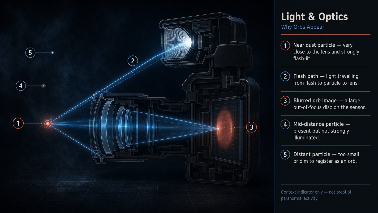
Orbs are a verified optical artefact. They are out-of-focus particles — dust, pollen, moisture droplets, lint, or small insects — captured very close to the lens inside the illumination zone of the flash. Because they sit within the lens's minimum focus distance, they cannot be rendered sharply; each particle is imaged as a "circle of confusion", an expanded circular disc of light [Ref 4, Ref 5]. The Orb Zone Theory (OZT), developed and tested by the Association for the Scientific Study of Anomalous Phenomena (ASSAP), formally explains the mechanism [Ref 5]. Its key predictions have been experimentally confirmed: orb frequency correlates with depth of field, not with location, and orb counts are not statistically higher in allegedly haunted locations than in non-haunted controls. Digital cameras produce far more orbs than film for a concrete reason. Digital sensors are physically smaller than a 35 mm film frame, so they need wider-angle lenses with much greater depth of field. That brings the near-focus zone — the orb zone — much closer to the flash, which on compact cameras is already mounted right next to the lens. The result is a flash-illuminated, near-field, out-of-focus sweet spot that reliably produces orbs. Larger orbs appear dimmer because the light from the particle is spread across a wider disc. Orbs never exceed roughly one-tenth of the frame size; if they were real objects at a distance, that upper limit would not exist. Lens flare and ghost images: When a strong light source — lamp, candle, streetlight, headlight — falls on or near the lens, it reflects repeatedly between the glass elements inside the lens, producing a string of secondary "ghost" images, usually symmetrical to the light source [Ref 6]. On night-vision cameras, IR illuminators produce the same kind of reflections off windows, mirrors, and other shiny surfaces.
Infrared, UV, and Full-Spectrum Camera Artefacts
Standard IR / night-vision cameras use an IR illuminator to light a scene at wavelengths the naked eye cannot see. This brings its own artefact set. Any reflective surface — glass, polished metal, mirrors, eyes — bounces a very high IR intensity back to the lens, causing localised saturation and "whiteout" patches. Motion blur under IR is also common: subjects near the illuminator are over-bright while the rest of the scene is underexposed. Full-spectrum cameras (modified to remove the internal hot-mirror filter) capture UV, visible, and near-IR wavelengths at once. This reveals fluorescent materials — certain fabrics, some paints, biological traces — that are invisible in normal light. The trade-off is more visual noise, a characteristic pinkish daylight colour cast, and the risk of misreading UV-fluorescent objects (reflective safety tape, certain cleaning products, some natural minerals) as anomalous [Ref 7]. Digital compression artefacts: Most cameras auto-compress video. Motion across the border between light and dark areas produces pixel smearing that can be misread as a moving translucent form in post-review.
Reflections, Light Intrusion, and Headlight Wash
Reflective surfaces — mirrors, windows, polished floors, glass display cases — can produce displaced images of investigators, equipment, or external light sources that appear to occupy a different part of the scene than they really do. In flash photographs, window glass can return the investigator's own reflection, sometimes only partially, creating a figure-like form. External light intrusion is a systematic contamination risk near roads. Moving vehicle headlights sweep through windows, casting fast-moving light shafts or momentary bright patches across walls. Security lights tripped by external movement can strobe a room. Streetlights — sodium or LED — push orange or blue-white ambient light through curtains and shutters. In a dark environment, any of these can register on camera as a transient light anomaly [Ref 8].
Temperature Gradients, Cold Spots, and Convection
"Cold spots" — localised drops in air temperature — are a staple of investigation reports. The physical explanations for them are well established in building science and thermodynamics. The most comprehensive published field study is Wiseman et al. (2003), carried out at Hampton Court Palace and the South Bridge Vaults, Edinburgh [Ref 9]. The team found that temperature drops in specific areas of Hampton Court's gallery lined up precisely with the positions of concealed doors — not with reports of supernatural activity. Air currents from the draughty old doors created localised temperature differentials. Notably, participants reported the most unusual sensations in those same areas regardless of whether they had been told anything about the location's reputation — which points to environmental factors (temperature, subtle air movement) driving the perception of "presence". Other physical causes of cold spots: Convection currents from differences in surface temperature cause cold air to pool along floors and near exterior walls. Building fabric variation: stone, brick, and tile have very different thermal mass to timber and plaster, so surfaces can feel cold to the touch even when the ambient air temperature is similar. Chimneys and flues: dormant fireplace openings and chimney-breast cavities create localised cold columns. Ventilation: HVAC ducts, suspended ceilings, cavity walls, and under-floor voids can deliver cold air to a room at floor or ceiling level with no visible source. A breath exhaled in cold air by an investigator creates a visible vapour cloud and a transient temperature drop that instruments can detect within about 30–60 cm.
Thermal Camera Misreads: Emissivity and Reflective Surfaces
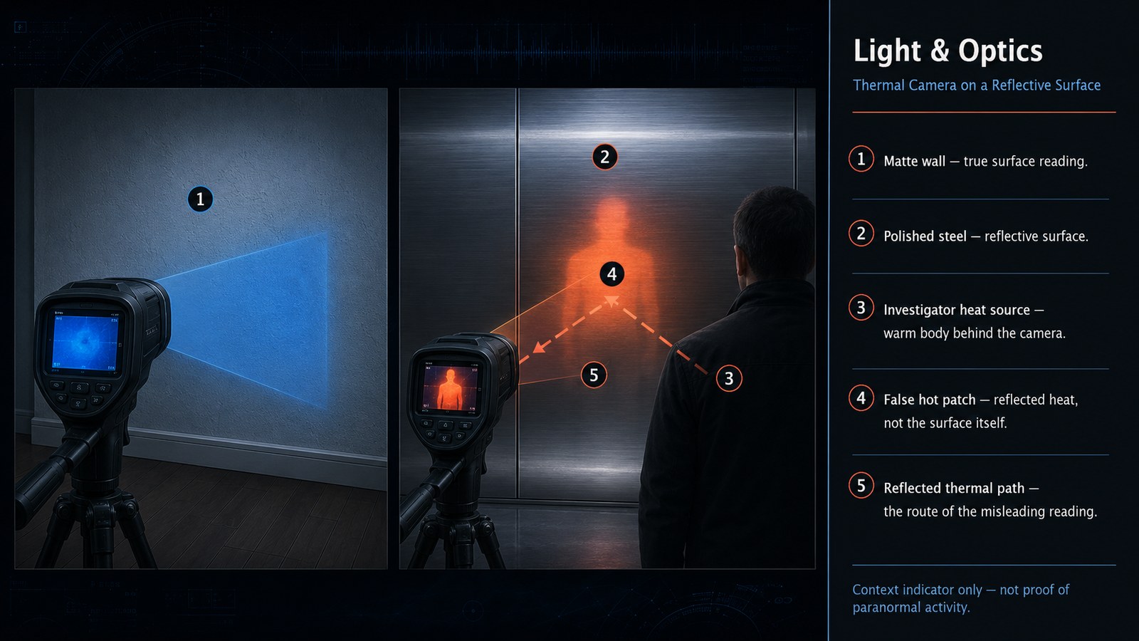
Thermal cameras do not measure temperature directly. They measure infrared radiation emitted from a surface, then calculate temperature using an emissivity value — a material constant for how efficiently a surface radiates heat relative to a perfect blackbody. Many investigators run a thermal camera on a single default emissivity (often 0.95, correct for skin and many organic materials) applied to every surface in the scene. The error this introduces can be dramatic. FLIR's own documentation [Ref 10] shows that applying an emissivity of 0.15 (right for polished stainless steel) to human skin at 36.7 °C produces a false reading of 98.3 °C. Set the other way, a reflective metal surface read at 0.95 will appear anomalously cold. Reflective surfaces are the single biggest false-positive generator for thermal cameras. Glass, polished metal, ceramic tiles, and glossy paint all have low emissivity (high reflectivity in the IR spectrum). They behave as IR mirrors: instead of measuring the surface itself, the camera reads the reflected thermal signature of surrounding objects — including the investigator's own body heat [Ref 11]. That readily produces apparent cold columns, warm patches, or "figures" on thermal footage that are nothing more than reflections. Humidity and condensation also shift thermal readings: a thin film of moisture on a cold surface raises its effective emissivity, warming its apparent temperature.
Low-Light Human Vision (Scotopic Vision)
In darkness or near-darkness the eye switches from cone-mediated colour vision to scotopic vision — rod-cell-mediated, monochromatic perception. This shift has several consequences that directly shape what investigators perceive [Ref 12, Ref 13]. No colour: rods carry a single pigment (rhodopsin) and cannot discriminate wavelength. Everything appears in shades of grey, so accurate colour-based identification of shapes is impossible in low light. Central scotoma: rods are absent from the fovea (the centre of the visual field). In very low light, you cannot see clearly what you are looking at directly — peripheral vision is more sensitive. Peripheral motion detection: rods are densely packed in the peripheral retina and highly sensitive to movement, and the visual system is wired to flag peripheral movement as urgent. This produces a strong tendency to perceive movement — a shape, a passing figure — at the edge of vision when nothing is there. It is sometimes called the "peripheral drift" effect. Slow adaptation and bleaching: rhodopsin bleaches when exposed to bright light (a torch, phone screen, camera flash) and takes 20–30 minutes to fully regenerate. An investigator checking their phone during a vigil is degrading their own night vision. Pattern completion and low spatial acuity: in very low light the visual cortex "fills in" incomplete edge information using contextual priors — the same top-down process that drives pareidolia. A coat on a hook, a person-shaped shadow, or a tall piece of furniture can all read as a standing figure.
Examples & documented cases
Wiseman et al., 2003 — Hampton Court Palace investigation
Published in the British Journal of Psychology (Vol. 94, pp. 195–211), this peer-reviewed study found that participants reported significantly more unusual experiences (sensed presence, temperature drop, unease) in areas with a local reputation for haunting — but this was not driven by prior knowledge of which areas were "haunted". Physical measurements identified draught-producing concealed doors as the source of the temperature anomalies in the key areas. The paper covers two sites: Hampton Court Palace (Surrey) and the South Bridge Vaults (Edinburgh). [9]
ASSAP Orb Zone Theory experiments
ASSAP (Association for the Scientific Study of Anomalous Phenomena) ran controlled photography tests that confirmed the two key OZT predictions: orb count varies with camera depth of field, and orbs are not statistically more common in haunted locations than in controls. The same orb does not appear simultaneously in stereo photography (confirmed separately by the Parascience group), which proves the object sits within centimetres of the lens, not metres away. [5]
fMRI study — neural mechanisms of face pareidolia
Liu et al. (2018), published in Scientific Reports / PMC, used fMRI in 20 participants to show that face pareidolia activated the right fusiform face area (FFA) and right prefrontal cortex to an identical degree as real face stimuli. It demonstrates the neural basis for why investigators reliably "see" faces in random textures, especially under pressure. [1]
FLIR emissivity error demonstration
FLIR Systems' published technical guidance documents an emissivity misconfiguration producing a temperature error of over 61 °C on a single surface — from a clinically safe 36.7 °C to a dangerous 98.3 °C. This is not a theoretical edge case; it is the default condition whenever a thermal camera is used on a metallic or gloss surface with factory settings. [10]
How it affects an investigation
Equipment involved
Standard digital cameras and smartphones — compact flash is an orb factory. DSLR / mirrorless cameras with external flash — lower orb risk, more lens flare from windows. IR / night-vision cameras and camcorders — IR reflections, compression artefacts. Full-spectrum cameras — UV/visible/near-IR at once; increased noise and UV-fluorescent false positives. Thermal cameras / FLIR imagers — emissivity and reflectivity errors. Point-and-shoot digital thermometers — cold-spot measurements; highly directional and affected by air movement and the body heat of the person holding them. Type K thermocouple loggers — slow response time means rapid cold-spot transients may be missed, while breath condensation in the probe housing creates false readings.
Artefacts and false perceptions
Dust near flash → Orb. Moisture/breath droplets near flash → Large bright orb. Small insect near flash → Multiple overlapping orbs, apparently moving. Lens flare from lamp/candle → Ghost image, light streak. IR illuminator on mirror or window → White saturation patch. Full-spectrum fluorescent material → Glowing area not visible to the eye. Peripheral rod vision → Perceived movement, fleeting figure. Pareidolia on textured surface → Face, figure, writing. Thermal camera on glass → Cold "figure" (reflected operator body). Thermal camera on polished metal → Wildly wrong temperature reading. Draughty concealed door → Localised cold spot. Investigator's exhaled breath → Vapour + detectable temperature drop.
What to check and control for
1. Dust audit, before and during. Note building fabric (stone dust, lime plaster, textiles), recent disturbance (access, cleaning), and humidity. 2. Flash and lens proximity. Keep the flash unit as far from the lens as possible — an off-camera flash eliminates orbs from that camera entirely. Ban dust-disturbing movement before photography. 3. External light mapping. Record road proximity, window positions, security lights, and their triggering angles before the vigil begins. Log all transient light events with timestamps. 4. Reflective surfaces. Catalogue every mirror, window, glass frame, polished floor, and metallic surface. Flag them in the logs before any thermal or photographic review. 5. Thermal camera emissivity calibration. Set the correct emissivity for each surface type — skin ≈ 0.97, painted wall ≈ 0.90, bare concrete ≈ 0.95, glass ≈ 0.84, polished steel ≈ 0.07–0.15. Use electrical tape to create a known reference patch on low-emissivity surfaces. 6. Cold-spot protocol. Take baseline readings at multiple heights and in adjacent rooms; use a calibrated data-logger rather than a handheld thermometer; identify all air-movement sources (doors, vents, flues, windows) before attributing a reading to anomaly. 7. IR illuminator positioning. Keep the illuminator off-axis from reflective surfaces; check the frame for window glass, mirrors, and other IR-bright surfaces before recording. 8. Investigator night-vision discipline. No bright lights for at least 20 minutes before a vigil; use red-light torches (red light bleaches rhodopsin more slowly); log all phone use during the vigil. 9. Photography at height. Orb zones sit typically within 30–60 cm of the lens; tilting the camera upward lowers the chance of capturing floor dust.
Contamination warnings
Recommended equipment
Infographics
On the map
View light-pollution & nearby-road context on the map
Most factors in this group are case-context factors, not spatial map layers — they describe conditions at a specific building and session, not a geographic feature that can be mapped continuously. The exception is external light intrusion, which is partially mappable. Light-pollution data can be sourced from the Light Pollution Map (lightpollutionmap.info) using VIIRS satellite data (free for non-commercial educational use; updated annually). Road proximity and streetlight density can be drawn from OpenStreetMap "highway" and "street_lamp" layers (ODbL licence, freely usable with attribution) and from OS Open Roads for Great Britain (OGL v3.0). A suggested PRN layer — "External Light Risk" — would derive a flag or score from distance to classified A/B roads and VIIRS-derived sky brightness, surfaced as a contamination prompt for headlight wash and ambient-light intrusion on the investigation location page.
Shown as context only — not evidence of paranormal activity.
Connected across PRN
What the evidence does not settle
"Paranormal orbs". A minority of researchers still distinguish "dust orbs" from orbs they class as anomalous on the basis of behaviour, internal structure, or trajectory. ASSAP's OZT accounts for all the structural variation observed to date — colour fringes, diamond shapes, apparent motion, apparent trailing — using known photographic physics, and no peer-reviewed study has confirmed a class of orb that the OZT cannot explain. (Lights observed in person, rather than on camera, are a separate phenomenon the OZT does not address.)
Pareidolia and genuine anomaly. Pareidolia explains why images get misread; it does not mean every image claim is pareidolia. It is a contamination flag, not a debunking tool.
Cold spots as physical anomaly. Wiseman et al. identified environmental explanations at two specific sites. The study does not claim that all cold spots everywhere have a draught-based explanation. It demonstrates the necessity of systematically ruling out building-fabric causes before classifying a temperature drop as anomalous.
Emissivity tables are approximate. Published emissivity values for building materials can vary by ±0.05 depending on surface finish, age, and contamination. That is an irreducible measurement uncertainty, and investigators should note it in their logs.
Scotopic perception research and paranormal application. The studies cited are general vision science. There is very little published research directly studying scotopic misperception in paranormal investigation contexts, so applying it to field conditions is an extrapolation. It is well supported by the underlying physiology, but it has not been formally tested in the field.
Sources
- [1] Neural mechanisms underlying visual pareidolia processing — fMRI study confirming fusiform face area (FFA) and prefrontal cortex activation in face-pareidolia identical to real face stimuli. NCBI/PubMed Central (peer-reviewed, Scientific Reports-adjacent), 2018 · Open access, CC BY
- [2] "The neural basis of face pareidolia with human intracerebral recordings" — direct cortical recording (n=44 patients), confirms VOTC face selectivity for pareidolic stimuli. MIT Press / Imaging Neuroscience (peer-reviewed), 2025 · Open access
- [3] Apophenia — definition and Klaus Conrad's 1958 origin; evolutionary basis for pattern-seeking in random data. Encyclopaedia Britannica, Continuously updated; entry current 2026 · Editorial; not CC — paraphrase only
- [4] "Orbs — FAQ" — plain-English summary of the circle-of-confusion / flash-proximity mechanism for orb formation. ASSAP (Association for the Scientific Study of Anomalous Phenomena), registered UK charity no. 327422, Article updated 2021 · ASSAP site content; quote with attribution
- [5] "Orb Zone Theory" — full technical explanation of the OZT; documents controlled experiments confirming depth-of-field and non-haunted-location predictions. ASSAP; authored by Maurice Townsend, Published/updated 29 January 2021 · ASSAP site content; quote with attribution
- [6] "Lens flare" — explanation of internal reflection mechanics and ghost-image formation in multi-element lenses. Wikipedia (secondary source); core optics content corroborated by Tamron technical documentation https://www.tamron.com/global/consumer/sp/impression/detail/article-what-is-camera-lens-flare-ghost-whiteout-blackout-vignetting.html, Continuously updated · Wikipedia CC BY-SA 4.0
- [7] "What Is A Full Spectrum Camera?" — explains UV/visible/IR capture, common artefacts including fluorescent false positives and pinkish daylight cast in modified cameras. SpiritShack (specialist paranormal equipment retailer, UK), Not dated; accessed June 2026 · Commercial site content; paraphrase only; supplement with primary optics sources
- [8] Vehicle headlight light pollution and intrusion — road vehicle headlights produce high-intensity horizontal illumination that travels long distances and penetrates roadside buildings. NCBI/PMC — Philosophical Transactions of the Royal Society B (peer-reviewed), 2018 · Open access
- [9] Wiseman, R., Watt, C., Stevens, P., Greening, E. & O'Keeffe, C. (2003) — "An investigation into alleged 'hauntings'", British Journal of Psychology, 94(2), 195–211. Temperature drops in Hampton Court gallery mapped to concealed-door draught positions, not to anomalous reports. The pre-eminent peer-reviewed haunted-location environmental study. Wiley / British Psychological Society (peer-reviewed), 2003 · Paywalled abstract; full PDF at http://www.richardwiseman.com/resources/BJP-hauntings.pdf (author-hosted)
- [10] FLIR Systems — "How does emissivity affect thermal imaging?" — documents 0.15 vs. 0.97 emissivity error producing 98.3 °C vs. 36.7 °C false reading on same surface. FLIR Systems (Teledyne FLIR) — thermal camera manufacturer, Accessed June 2026 · Commercial documentation; paraphrase with attribution
- [11] Fluke Corporation — "Fixing Infrared Thermography Issues on Reflective Surfaces" — explains IR mirror effect on low-emissivity surfaces, reflected body-heat false readings. Fluke Corporation (test instrument manufacturer), Accessed June 2026 · Commercial documentation; paraphrase with attribution
- [12] "Physiology, Night Vision" — StatPearls/NIH — rod cell distribution, scotopic sensitivity, foveal scotoma, colour loss, and peripheral motion detection under low-light conditions. StatPearls/NCBI (peer-reviewed educational resource), Continuously updated; 2023 review · Free-access NCBI Bookshelf
- [13] "Seeing in the dark: High-order visual functions under scotopic conditions" — 2024 review of rod-mediated visual processing, motion detection, and perceptual limitations in darkness. PMC / iScience (Cell Press, peer-reviewed), 2024 · Open access, CC BY
Further reading
- ASSAP — Orb Zone Theory (full technical explanation and experimental results) — ASSAP
- ASSAP — Orb FAQ (plain-English investigator guide) — ASSAP
- Wiseman, R. et al. (2003) — "An investigation into alleged hauntings" (British Journal of Psychology, open abstract) — Wiley / British Psychological Society
- FLIR — "How does emissivity affect thermal imaging?" — FLIR Systems (Teledyne FLIR)
- Fluke — "Fixing Infrared Thermography Issues on Reflective Surfaces" — Fluke Corporation
- NIH/PMC — "Seeing in the dark: High-order visual functions under scotopic conditions" (2024) — PMC / iScience (Cell Press)